IKEA Hydroponics Upgrade
I wanted to add some smarts to the IKEA KRYDDA/VAEXER hydroponics system that sits in my workshop. The unit is technically on loan from my friend Matthew, but I might just have to buy him another one. Though all these upgrades are designed to be entirely reversible.
The system combines mostly cheaply available components and 3D printed models. The code and intelligence all comes from ESPHome and Home Assistant, but you could easily add your own.
Features so far include:
Webcams to remotely monitor plant health
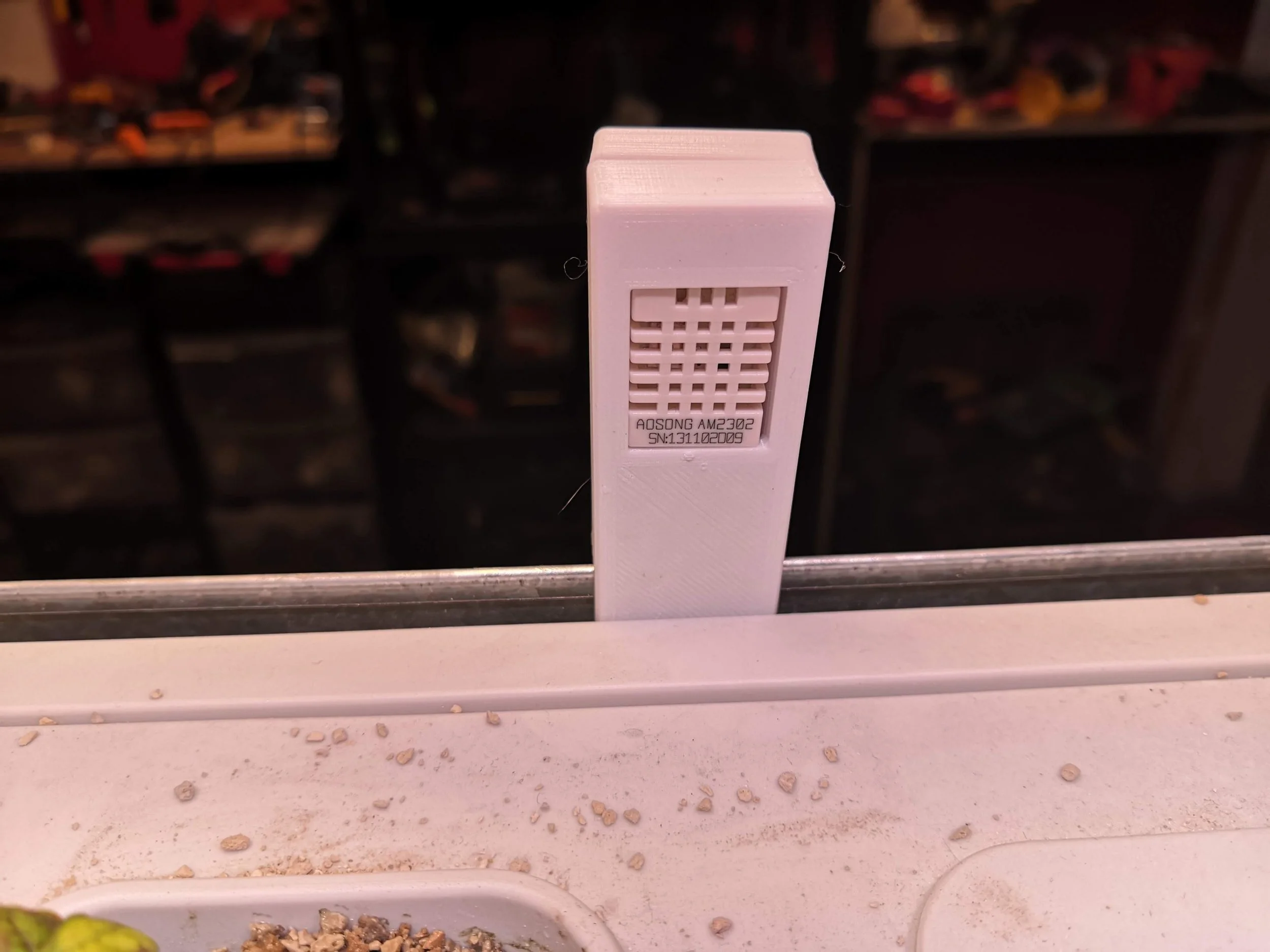
Temperature and humidity monitoring at each level
Remote control of lights with scheduling
Monitoring of water levels with alarms sent to mobile
Whole system operates off one mains plug
I'm considering adding light level monitoring and maybe automated top-up of the water levels from a reservoir. And one day, using a camera and some sort of computer vision system to track growth. Then you could use machine learning to optimise light patterns and feeding. Maybe even a robot arm for harvesting…
What I Learned
This has been a brilliant project to help me understand the challenges of urban farming and food production, from the efficiency of artificial light sources, to the challenges of monitoring, to issues around pollination. It has also been a great project for recycling: the water level sensors were harvested from a scrap photocopier that I stripped down to see what parts I could reuse.


Bill of Materials (BOM)
This is as close to the parts I've used as possible. Bear in mind there may be differences - e.g. in sizes and mounting holes, so check and adjust before you print things.
I've used Amazon for reference as I have an affiliate account with them, but all these parts are available in lots of places at varying prices, depending on how long you're prepared to wait.
NodeMCU x1 (Amazon)
NodeMCU Base x1 (Amazon)
Arduino Pro Mini x1 (Amazon)
DHT-22 Temperature and Humidity Sensor x2 (Amazon)
Optical interruption sensors x4 (Amazon)
4-way relay board (Amazon)
12v switching PSU (Amazon)
Veroboard/stripboard (Amazon)
Female-to-Female Dupont hook-up wires (Amazon)
Ribbon cable or hook-up wire (Amazon)
Level shifter (Amazon)
6-core alarm cable (Amazon)
6-pin panel-mount DIN sockets x4 (Amazon)
6-pin DIN plugs x4 (Amazon)
IEC three pin power socket (Amazon)
IEC power cable (Amazon)
2.5mm mains cable (rated to 13A see below) (Amazon)
PLA filament (Amazon)
Knurled M3 threaded inserts (Amazon)
Connecting blocks or Wago snap blocks (easier) (Amazon)
Rubber grommets (O/D 10mm)
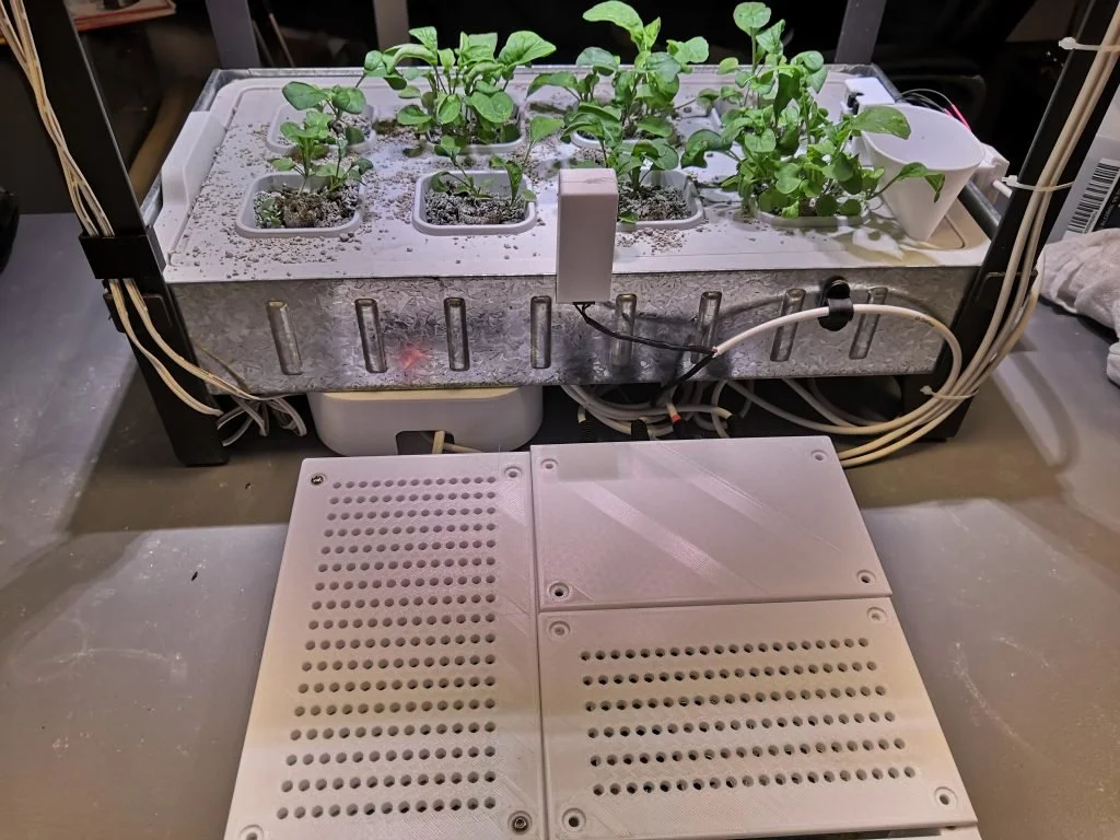
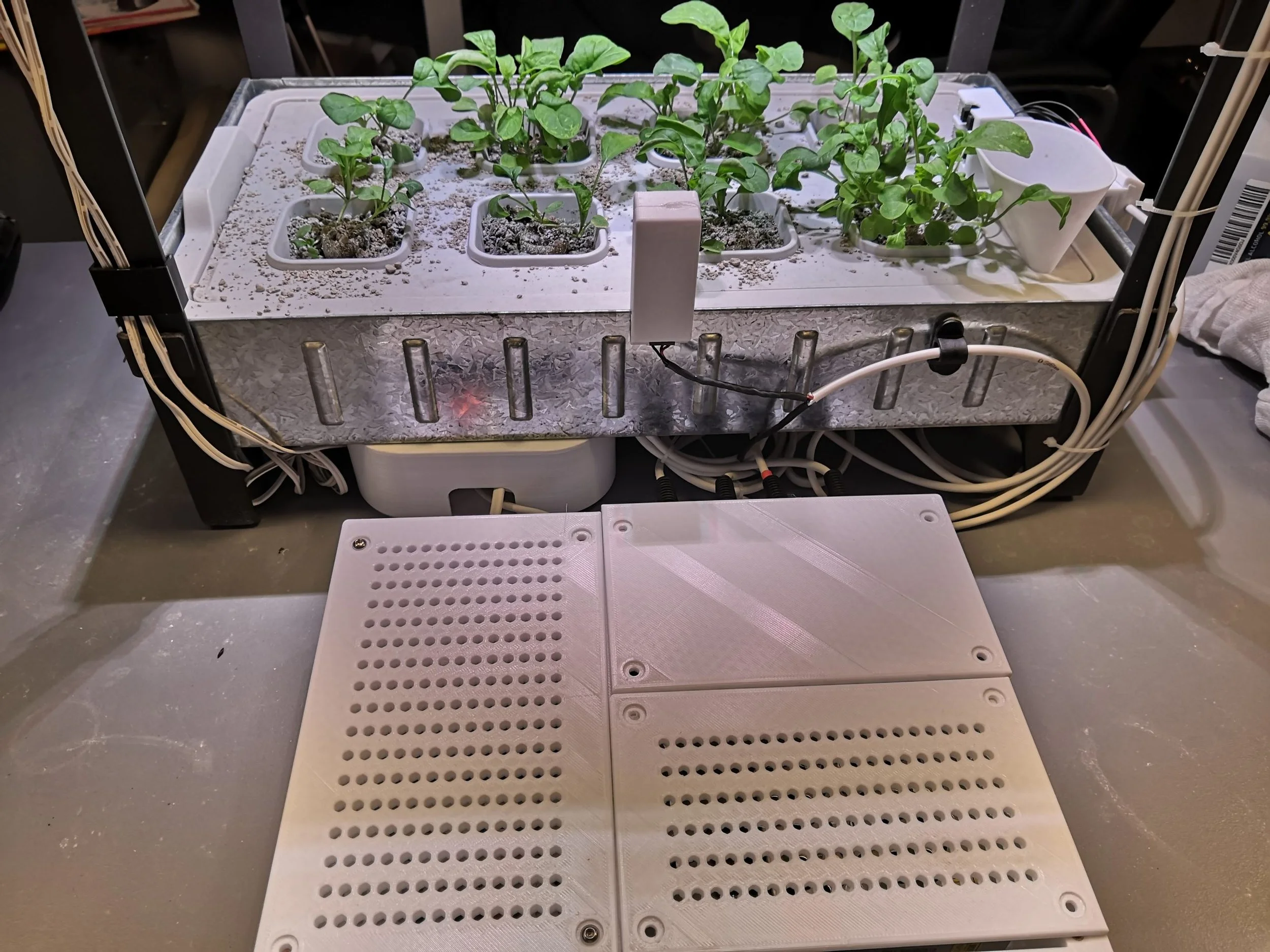
Design Files
I've included the STL files here for you to download. This includes the rough sketches of the components I made to help me size everything and lay out mounting holes etc. These can be loaded straight into Cura or whatever slicer you use for your 3D printer. But you may well want to tweak and remix the files, since I'm hardly the greatest designer and there will definitely be some tweaks to make to fit the specific components you use. If that's the case, follow the link for the full set of Fusion360 files which can be downloaded in a variety of formats.
Case: STL files (archive) Fusion360 files from AutoDesk
Cable Clip:STL files (archive) Fusion360 files from AutoDesk
Code
This is the ESPHome sketch I use. You will need to install the relevant sketch on the Arduino and follow the instructions for the Arduino Port Expander over at ESPHome.io
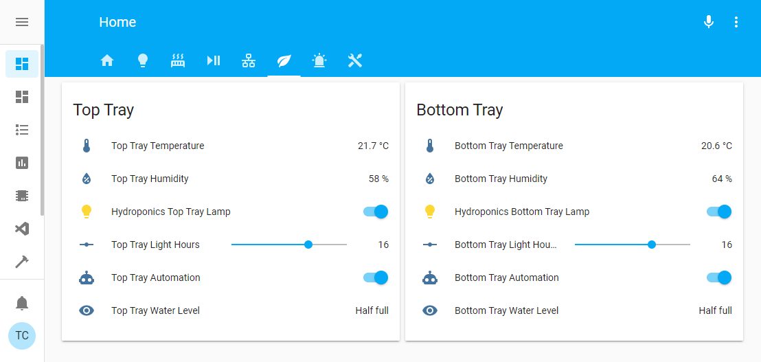
esphome:name: hydroponics_monitorplatform: ESP8266board: nodemcuv2includes:- arduino_port_expander.hwifi:ssid: "YOUR_SSID"password: "YOUR_PASSWORD"manual_ip:static_ip: THE.UNIT.IP.ADDRESSgateway: YOUR.GATEWAYsubnet: 255.255.255.0use_address: hydroponics_monitor.local# Enable fallback hotspot (captive portal) in case wifi connection failsap:ssid: "Hydroponics Fallback Hotspot"password: "CHOOSE_A_PASSWORD"captive_portal:# Enable logginglogger:# Enable Home Assistant APIapi:password: "YOUR_API_PASSWORD"ota:password: "YOUR_OTA_PASSWORD"i2c:id: i2c_componentcustom_component:- id: apelambda: |-auto ape_component = new ArduinoPortExpander(i2c_component, 0x08);return {ape_component};output:- platform: customtype: binarylambda: |-return {ape_binary_output(ape, 6),ape_binary_output(ape, 7),ape_binary_output(ape, 8),ape_binary_output(ape, 9)};outputs:- id: output_pin_6inverted: true- id: output_pin_7inverted: true- id: output_pin_8inverted: true- id: output_pin_9inverted: trueswitch:- platform: outputname: "Top Tray Lamp"output: output_pin_6- platform: outputname: "Bottom Tray Lamp"output: output_pin_7- platform: outputname: "Relay 3"output: output_pin_8- platform: outputname: "Relay 4"output: output_pin_9binary_sensor:- platform: statusname: "Hydroponics Status"- platform: customlambda: |-return {ape_binary_sensor(ape, 10),ape_binary_sensor(ape, 11),ape_binary_sensor(ape, 12),ape_binary_sensor(ape, 13)};binary_sensors:- id: binary_sensor_pin10name: "Top Tray Water Half"- id: binary_sensor_pin11name: "Top Tray Water Full"- id: binary_sensor_pin12name: "Bottom Tray Water Half"- id: binary_sensor_pin13name: "Bottom Tray Water Full"sensor:- platform: wifi_signalname: "Hydroponics Wifi Signal"update_interval: 60s- platform: uptimename: "Hydroponics Uptime Sensor"- platform: dhtpin: D3model: DHT22temperature:name: "Top Tray Temperature"humidity:name: "Top Tray Humidity"update_interval: 60s- platform: dhtpin: D4model: DHT22temperature:name: "Bottom Tray Temperature"humidity:name: "Bottom Tray Humidity"update_interval: 60sMost of the configuration is done through the Home Assistant front end, but I did need to delve into some YAML for the template sensor that translates the output of the two optical sensors into a reading of 'Full', 'Half-full', 'Empty', or 'Error', if the sensors are reading oddly (e.g. top one closed but bottom one open).
Here's the YAML:
- platform: templatesensors:top_tray_water_level:friendly_name: "Top Tray Water Level"value_template: >-{% if is_state('binary_sensor.top_tray_water_full', 'off') and is_state('binary_sensor.top_tray_water_half','off') %}Empty{% elif is_state('binary_sensor.top_tray_water_full', 'off') and is_state('binary_sensor.top_tray_water_half','on') %}Half full{% elif is_state('binary_sensor.top_tray_water_full', 'on') and is_state('binary_sensor.top_tray_water_half','on') %}Full{% else %}Error{% endif %}bottom_tray_water_level:friendly_name: "Bottom Tray Water Level"value_template: >-{% if is_state('binary_sensor.bottom_tray_water_full', 'off') and is_state('binary_sensor.bottom_tray_water_half','off') %}Empty{% elif is_state('binary_sensor.bottom_tray_water_full', 'off') and is_state('binary_sensor.bottom_tray_water_half','on') %}Half full{% elif is_state('binary_sensor.bottom_tray_water_full', 'on') and is_state('binary_sensor.bottom_tray_water_half','on') %}Full{% else %}Error{% endif %}Notes on the design
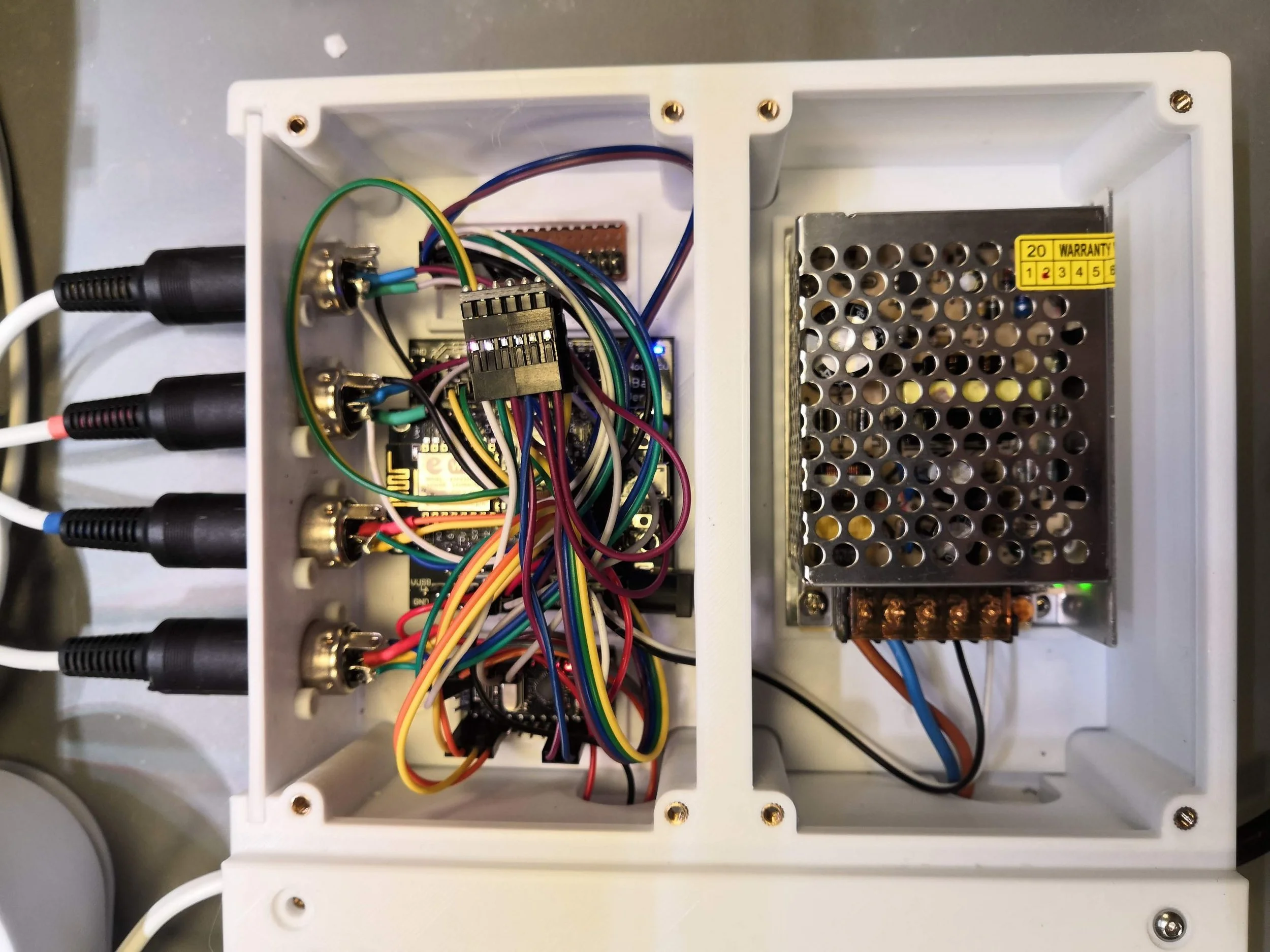
The Arduino
I love the ESP8266. But sometimes you need more ports. And sometimes you want 5V logic. A real engineer would probably find a nicer solution than this. But ESPHome makes it *so* easy to bolt on an extra few ports and 5V logic with a little cheap Arduino (thanks again Otto). And fundamentally I'm about making things that work, not that are ready for mass production.
Temperature and humidity monitoring
I put this in at each level because initially I had the covered seed tray in one level and the actual plants in the other. I figured it would be good to measure the conditions inside the cover. It's probably not necessary when you have the growth trays at each level, though you do see a big variation in temperature and humidity across the two. Could just be inaccuracy in the sensors though? An upgrade away from the DHT models is probably wise.
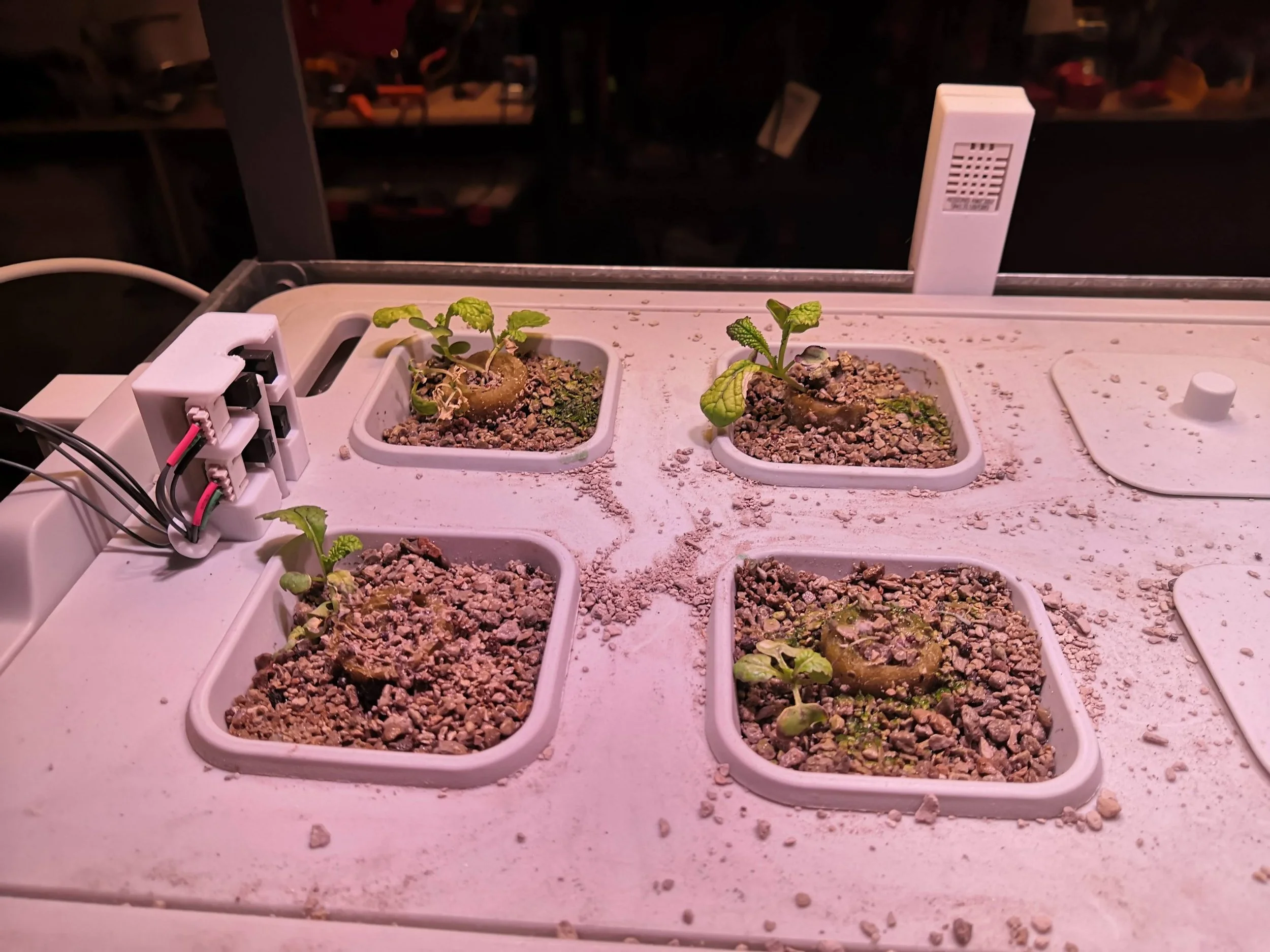
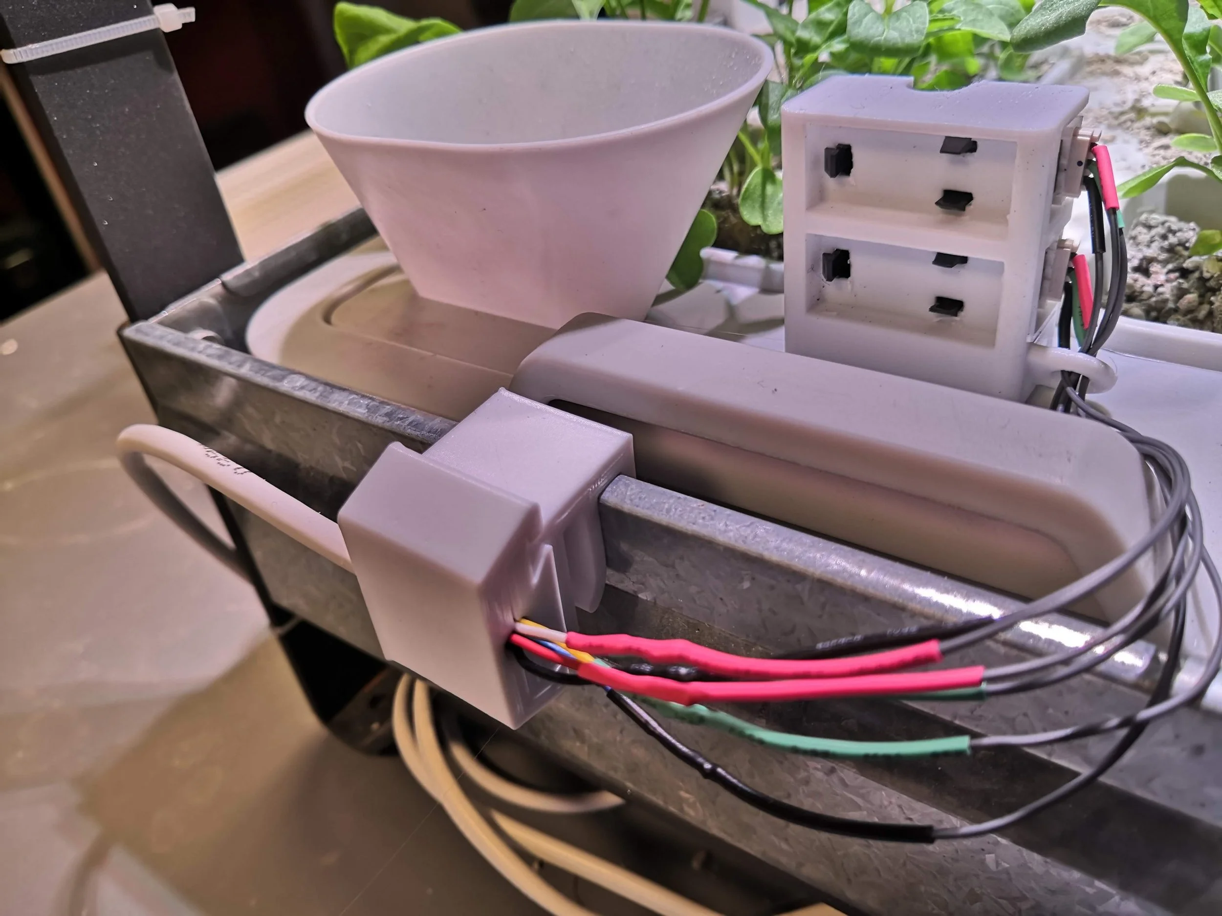
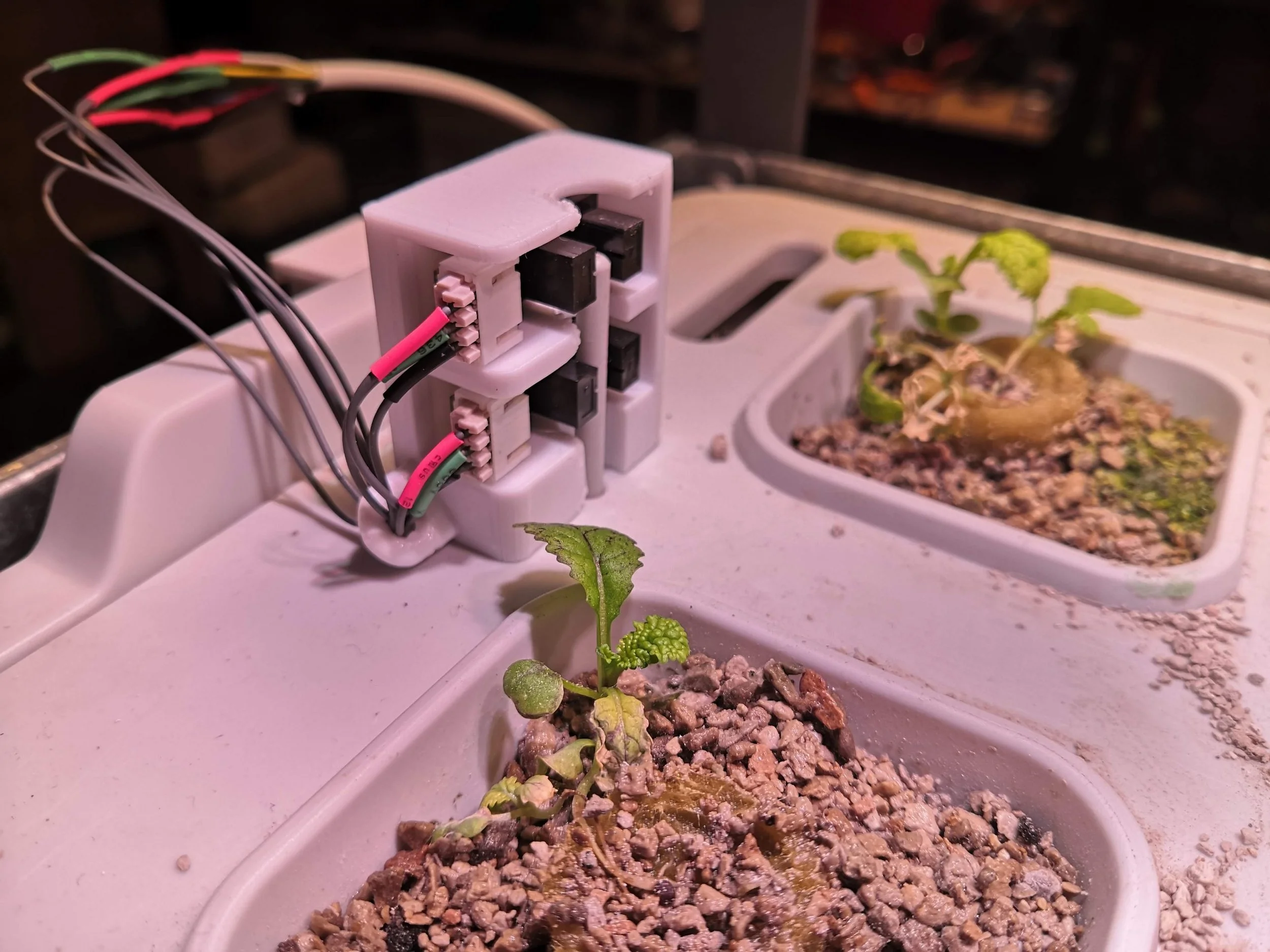
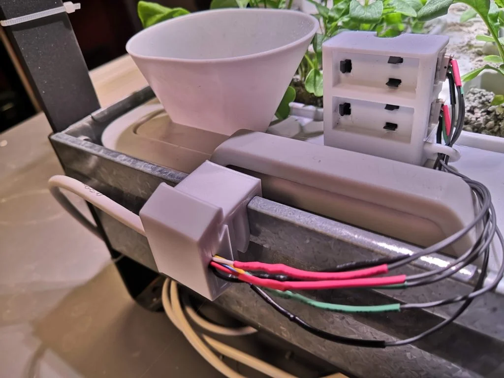
Water level monitoring
I ended up using a mechanical solution for this, based on the existing float system. I initially tried an electrical system with a forked contact plate in the growing medium, but because of all the electrolytes in the water (I'm guessing), these corroded incredibly quickly and failed.
The sensors I am now using were harvested from a broken photocopier I bought for £1. If you like making stuff and want loads of cool parts for next to nothing, I can highly recommend doing this. But this does mean my 3D models might not fit the alternatives I have listed in the bill of materials above and you'll need to do some adaptation.
Mains wiring
This device switches mains electricity. That means you need to be very careful with what you're doing! I've used lengths of colour-coded wire with a cross section of 2.5mm squared, rated for 13A. This is arguably overkill, since it is only driving two lamps rated at 10W and a 24W PSU. Obviously, I take no responsibility for how you use this design. But I would not recommend using these little relays to switch something more power-hungry.